Introduction
We use crossover filters to partition the frequency bands between drivers in a multiway speaker. In addition, the crossover filter may provide EQ such as baffle-step compensation. A passive crossover filter sits between the power amplifier and the drivers. The textbook filter examples typically assume that the driver represents a resistive load. However, a woofer in a sealed or reflex box has an impedance very far from being purely resistive. In fact, the impedance has one or more huge peaks with high phase angles. This post studies the effect of just adding a series inductor to a woofer. All woofer filters will have such series inductor in order to provide the needed low pass filtering of the signal fed to the woofer. The surprising result is that a series inductor effectively changes the woofer parameters such that its moving mass is seemingly reduced.
PTT 10.0X04 in a Sealed Box
Using the Vituix CAD enclosure tool we select the PTT10.0X04 woofer and choose sealed box with Qtc=0.701 (Butterworth) tuning. This is achieved in a sealed box of 50.3 liters yielding F3=fc of 55Hz
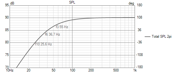 <graph>
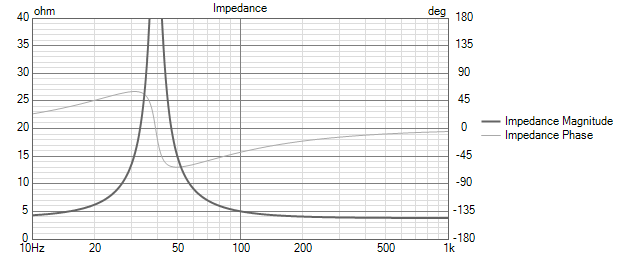
The impedance has a large resonant peak at fc:
Now we add a series inductor of 2mH in the enclosure tool in order to low-pass the woofer response and save the response without a filter as an overlay. Such inductor is typical for use in a 3 way system where the crossover frequency to the midrange is at a few 100 Hz. Also, baffle-step compensation for a large box requires an inductor of a similar value.

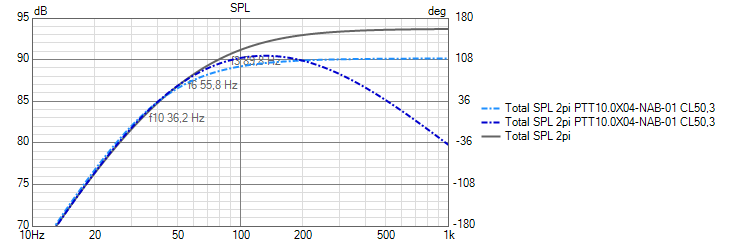
We note that we indeed get a low-pass action but surprisingly the response actually peaks more than a dB over the no inductor response. This boost is reflected in the combined impedance is reduced by the inductor in the frequency range where we have the boost:
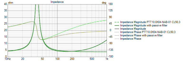
The reduced impedance around 100Hz accounts for the more energy pulled out of the amplifier to give the boost.
Seemingly Reduced Mms
Now we replace the inductor with an active 1st order low-pass filter and see if we can match the response of the woofer with the 2mH in series. Obviously, this can only give the low-pass response but not give the boost we observe. In order to explain the boost we need to modify the woofer parameters to yield a higher sensitivity. This sensitivity boost is a side effect of a passive filter which is not explained by its active counterpart (which sits before the power amp and does not interact with the driver impedance). It turns out by experimentation that we get a very good match but reducing the Mms of the woofer from 98g to just 65g and set the 1st order low-pass to 203Hz:

The reduced Mms increases the sensitivity but does not change the asymptotic low-frequency response since this is set by the unchanged motor strength and unchanged compliance of the woofer and air in the box.
An increase in the motor strength (Bl product) would also mirror an increased sensitivity but the low frequency asymptote would change too and thus not fit with what we observe. Consequently, the apparent reduction in Mms is the best model for the retuning of the bass response.
Removing the Low-Pass
Removing the active low-pass shows the effect of the reduced Mms. The woofer behaves like a woofer with reduced Mms.
We see that we gain about 3.6dB sensitivity which is expected from the reduction in Mms (20log10(98/65) = 3.6dB). This is accompanied by an increase in the corner frequency (less bass extension).
What About Thiele-Small Parameters and Box Alignment?
Reduction of Mms reduces Qts and increases fs by the square root of the relative change in moving mass, e.g., if Mms is reduced by 10% we get around 5% reduction in Qts and around a 5% increase in fs. The Vas and Sd is unchanged. Now, what is the effect on the possible box tuning? A reduced Qts means that we need to reduce the box volume to preserve the alignment, e.g., maintain a certain fc or stick to e.g., the QB3 alignment. Now, since fs is increased we also increase F3 which is further aggravated by the reduction in Qts. However, the reduced bass extension is to be expected from Hofmann's infamous iron law since we get both higher sensitivity and reduced box volume.
Precompensating the Alignment for the Reduction in Mms
We will look at a reflex box example where we use the newly gained knowledge of the reduced Mms to to a pre-compensated box tuning that works with the simple crossover filter consisting of the 2mH series inductor. Using the reduced Mms woofer (65g) we compute the QB3 alignment in Vituix CAD yielding a box of only 20.6 liters and a reflex tuning of 41.7Hz :
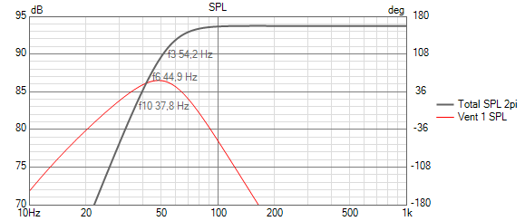
The above is our textbook target alignment and we can add our 203Hz 1st order active low-pass filter (which sits before the power amp and does not interact with the driver impedance) to get our target response including the target filter response:

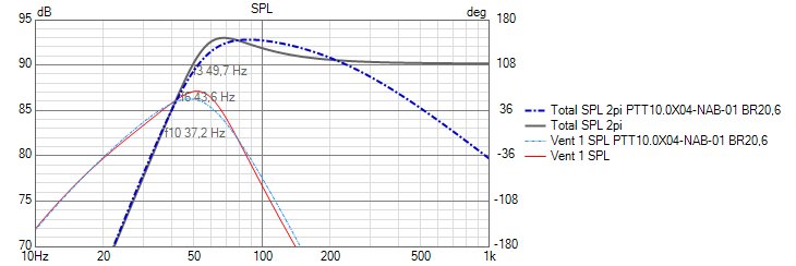
We save the above response as an overlay and switch back to the unmodified Mms (98g) woofer and add the 2mH inductor in, and turn off the active filter to observe if we get the same response. Again maintaining the box tuning (20.6 liters and fb=41.7Hz):

The response using the real (98g) woofer and 2mH series inductor indeed is a very close to match to the target response of the QB3 response of the hypothetical 65g woofer with the active low-pass. We conclude that the reduced Mms model is also working reasonably well for the reflex box case.
Removing the inductor again reveals the raw box tuning we used:
We see that this tuning without the passive filter (precompensated box tuning) peaks by around 3dB which is contributing to the effective 3.6dB increase in apparent sensitivity we have gained by adding the 2mH inductor.
Alternative Compensation: Adding Series Resistance
The reduction in Mms is as mentioned causing a seeming reduction in Qts which pushes the box tuning in the direction of smaller box. To counter that, we can increase the effective Qts by adding a series resistance to the woofer. This trades some of the sensitivity gain caused by the inductor to get more bass extension at the expense of a larger box.
Optimising the Combined Response Numerically
A typical crossover filter network is more complex than just a series inductor and typically has capacitors shunting the signal to increase the roll off slope. This means that the Mms reduction model becomes too simplistic. Luckily, the huge computing resources of modern desk top PCs are more than adequate to optimise the combined response numerically. This technique was used in the SPK 16 Reference Design Blog Post where the box tuning and passive filter was co-optimised numerically including addition of a significant amount of series resistance to improve the bass extension.
Conclusion
The interaction between the driver impedance and a passive filter network is fairly complex. A textbook bass alignment may no longer work when using a textbook crossover filter. For the simple case of a series inductor, we have shown that the bass alignment effectively is re-tuned corresponding to if the driver Mms was reduced. In the general case, we can co-optimise the bass alignment and passive filter to yield a desireable combined ressponse. We will provide examples of this in a follow up post.